


Click image to enlarge
PHP mechanical pump-in proportional mixing device
Retail price
Market price
Weight
kg
Stock
隐藏域元素占位
Key words:
Mechanical pump-in proportional mixing device
- Product Description
-
- Commodity name: PHP mechanical pump-in proportional mixing device
Product Introduction
The mechanical pump-in proportional mixing device is a flow-balanced proportional mixing device, which is composed of a water turbine (non-drainage type), a foam liquid pump, a coupling, a valve, a piping system, a PLC control cabinet, a foam liquid storage tank and a base. The unit consists of two key components: a water turbine and a foam pump. The fire water flowing in the pipeline is used as the driving force, and the foam liquid pump is driven by the water turbine to extract the foam liquid in the atmospheric pressure tank and pump it into the main fire pipeline. Through the matching of the internal structural parameters of the water turbine and the foam liquid pump, the flow rate of water and the flow rate of foam liquid are balanced, and the proportional mixing is realized. When the three-way valve on the pipeline system closes the suction port, the foam pump will automatically clean.
It is mainly suitable for large, medium and small foam fire fighting systems in substations, underground parking lots, petrochemicals, ports, oil depots, airports (depots), offshore platforms and other places.Working principle
The fire water flows through the water turbine. The water turbine rotates and drives the plunger pump. The plunger pump sucks the foam liquid, pressurizes it and injects it into the outlet of the water turbine, and mixes it with water to form a foam mixture. The amount of foam liquid is proportional to the flow rate and is independent of the pressure change, so that a stable mixing ratio can be guaranteed under the condition of pressure change.
Because water needs to consume a certain amount of energy to do work, the fire water flowing through the hydraulic motor will have a certain pressure loss. The pump-in proportional mixing device produced by our company has a pressure loss of fire water within 0.15MPa under the working pressure of 1.6MPa.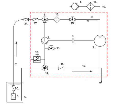
Working Schematic Diagram
1. Fire water supply 2, water turbine (non-drain type) 3, plunger pump 4, coupling 5, foam liquid supply 6, bottom filter 7, suction pipe 8, three-way ball valve (flushing/suction) 9, flushing pipe 10, fire water pipe 11, check valve 12, injection pipe 13, exhaust pipe 14, fire water filter 15, flushing pipe 16, flushing pipe filter 17, suction pipe swing check valve 18, pressure release valve 19, tee (mixing/return) 20, bottom valve 21, suction pipe exhaust
Product advantages
1. It is suitable for all foam fire extinguishing systems and can replace pressure proportional mixing device and balanced proportional mixing device with accurate mixing ratio.
2. Easy to install, hydraulic drive, no additional power required. Compact, light weight, no pressure vessel required.
3. Simple to use, simple mechanical mixing, wide flow range, wide pressure range, no correction required.
4. Economical and efficient, simple maintenance, simple regular testing, low maintenance cost during the use period.Technical parameters
Model specifications
Flow range
(L/S)
Working pressure range
(MPa)
mixing ratio
(%)
Supervisor caliber
A(mm)
Foam liquid inlet
C(mm)
Return port
B(mm)
Pressure relief port
D(mm)
L(mm)
H(mm)
W(mm)
X(mm)
PHP8
1~8
06~1.2 or 0.6~1.6
3% or 6%
DN50
1〞
1/2〞
1/2〞
700
250
400
350
PHP16
3~16.6
DN65
1〞
1/2〞
1/2〞
850
260
450
350
PHP25
3~26.5
DN100
11/2〞
1〞
3/4〞
990
350
500
400
PHP40
4.2~40
DN100
2〞
1〞
3/4〞
1200
350
500
450
PHP66
8~66.5
DN150
2 1/2〞
1〞
3/4〞
1250
400
600
500
PHP100
8~100
DN200
21/2〞
11/2〞
1〞
1450
550
600
550
PHP135
8~135
DN250
21/2〞
11/2〞
DN40
1750
1000
1000
700
PHP170
18~170
DN300
21/2〞
2〞
DN50
1800
1050
1000
700
PHP250
20~250
DN350
DN100
DN65
DN65
2800
1200
1600
950
PHP335
30~335
DN400
DN125
DN65
DN65
2800
1180
1600
950
System Control
The mechanical pump-in proportional mixing device adopts PLC automatic control system, which can well solve the problem that when a fire occurs in the case of unattended operation, the opening and closing of the inlet valve and the inlet valve are controlled according to the set program at the first time to start or close the device, and the state signal of corresponding action is displayed on the control cabinet at the same time. Can accept the automatic fire alarm signal of the central control and implement automatic fire extinguishing accordingly.
The control system has two modes: automatic control and on-site manual control.1) Automatic control
When the control cabinet is in the automatic control mode, the PLC control system receives the fire alarm signal or manually confirms the fire according to the information of the fire alarm system and manually opens the start button of the fire control room device. After receiving the instruction, the device control system automatically opens the main system fire water inlet valve (normally closed) and foam liquid inlet valve (normally closed), and detects whether the foam liquid pump is normally started through the main foam liquid pump outlet pressure transmitter, when the outlet pressure of the foam liquid pump reaches the set value (≥ 0.6MPa), it means that the pipe network pressure has been established and the main system has been successfully started; if the pump outlet still does not reach the set value 30s (adjustable) after the foam liquid pump is started, the device system will give an alarm, the main system will stop and automatically switch to the standby system.
When any control equipment of the main system in the unit fails, alarm will be given and the standby system will be started in turn. The alarm signal can be uploaded to the fire control room fire linkage controller, in the fire control room alarm.2) On-site manual control:
In case of fire, directly start the device into operation by operating the button on the control cabinet of the device. The operation of the device is automatically controlled by the control cabinet program. The control cabinet program control process is the same as above. If the electric valve fails to start, it can also be opened directly by mechanical manual. After the fire is put out, close all electric devices on site through the button on the field control cabinet.
Installation of device
1. Check whether the skid of the mechanical pump-in proportional mixing device is damaged during transportation.
2. Use a lifting tool to place the mixing device skid on the equipment installation foundation and fix it with anchor bolts.
3. Install the foam tank on its foundation and fix it with anchor bolts. After the foam tank is fixed, install the accessories of the foam tank such as liquid level gauge and breathing valve to the corresponding position of the foam tank.
4. Correctly connect the fire water inlet on the skid block and the foam mixed solution outlet with the main pipe, and correctly connect the foam stock solution inlet and the foam stock solution return port with the foam stock solution outlet and the foam stock solution return port on the foam tank.
5. After the equipment is installed, check whether the flange connecting bolts of the skid block pipeline are loose during transportation. If there is any looseness, please tighten it again to prevent leakage.
Inspection and preparation before device start-up
1. Foam tank inspection: open the manhole cover of the foam tank and check whether there is dust, dirt and stains in the foam tank. If so, rinse the foam tank with clean water and let it dry.
2. Foam liquid filling: Before filling foam liquid, please check whether all valves of the foam tank are closed to prevent leakage and loss of foam liquid. It is recommended to use a liquid filling pump to pump into the foam tank from the liquid filling port of the tank. If there is no liquid filling pump, it can only be injected from the manhole of the tank top (it is better not to pour from the manhole, so a large amount of foam will be generated when filling the foam liquid, which is easy to overflow). When excessive foam is generated during the filling of foam liquid, please stop filling and continue filling after the foam disappears to prevent overflow.
3. Check the switch status of each valve of the skid.
4. Start the fire pump to supply water to the main pipe of the skid block. At this time, open the fire water inlet valve and the foam liquid inlet valve, and the system will run in the working state.
Flushing after unit operation
1. After the operation of the foam system is completed, the skid pipe, foam pump and valve shall be flushed with clean water.
2. When flushing the system, the valves of the system shall be adjusted to the flushing position according to the requirements of the system valve switch state table.
3. When the system valve is adjusted to the flushing state, the flushing time is about 2 to 5 minutes, and the discharged water no longer contains foam.
4. After flushing, the valves of the system must be restored to the standby state and ready to run again at any time.
Product Introduction
The mechanical pump-in proportional mixing device is a flow-balanced proportional mixing device, which is composed of a water turbine (non-drainage type), a foam liquid pump, a coupling, a valve, a piping system, a PLC control cabinet, a foam liquid storage tank and a base. The unit consists of two key components: a water turbine and a foam pump. The fire water flowing in the pipeline is used as the driving force, and the foam liquid pump is driven by the water turbine to extract the foam liquid in the atmospheric pressure tank and pump it into the main fire pipeline. Through the matching of the internal structural parameters of the water turbine and the foam liquid pump, the flow rate of water and the flow rate of foam liquid are balanced, and the proportional mixing is realized. When the three-way valve on the pipeline system closes the suction port, the foam pump will automatically clean.
It is mainly suitable for large, medium and small foam fire fighting systems in substations, underground parking lots, petrochemicals, ports, oil depots, airports (depots), offshore platforms and other places.
Working principle
The fire water flows through the water turbine. The water turbine rotates and drives the plunger pump. The plunger pump sucks the foam liquid, pressurizes it and injects it into the outlet of the water turbine, and mixes it with water to form a foam mixture. The amount of foam liquid is proportional to the flow rate and is independent of the pressure change, so that a stable mixing ratio can be guaranteed under the condition of pressure change.
Because water needs to consume a certain amount of energy to do work, the fire water flowing through the hydraulic motor will have a certain pressure loss. The pump-in proportional mixing device produced by our company has a pressure loss of fire water within 0.15MPa under the working pressure of 1.6MPa.
Working Schematic Diagram
1. Fire water supply 2, water turbine (non-drain type) 3, plunger pump 4, coupling 5, foam liquid supply 6, bottom filter 7, suction pipe 8, three-way ball valve (flushing/suction) 9, flushing pipe 10, fire water pipe 11, check valve 12, injection pipe 13, exhaust pipe 14, fire water filter 15, flushing pipe 16, flushing pipe filter 17, suction pipe swing check valve 18, pressure release valve 19, tee (mixing/return) 20, bottom valve 21, suction pipe exhaust
Product advantages
1. It is suitable for all foam fire extinguishing systems and can replace pressure proportional mixing device and balanced proportional mixing device with accurate mixing ratio.
2. Easy to install, hydraulic drive, no additional power required. Compact, light weight, no pressure vessel required.
3. Simple to use, simple mechanical mixing, wide flow range, wide pressure range, no correction required.
4. Economical and efficient, simple maintenance, simple regular testing, low maintenance cost during the use period.
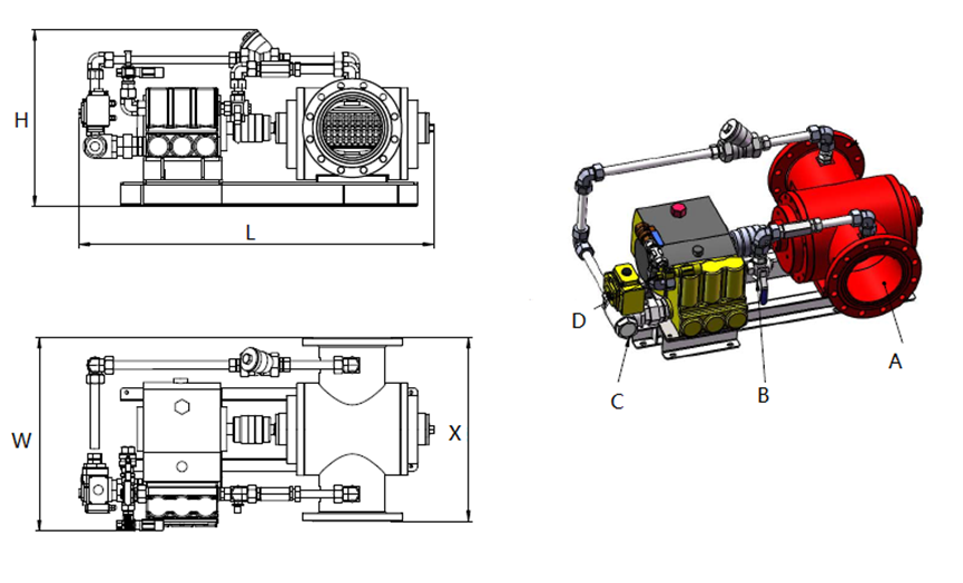
Technical parameters
|
Model specifications |
Flow range (L/S) |
Working pressure range (MPa) |
mixing ratio (%) |
Supervisor caliber A(mm) |
Foam liquid inlet C(mm) |
Return port B(mm) |
Pressure relief port D(mm) |
L(mm) |
H(mm) |
W(mm) |
X(mm) |
|
PHP8 |
1~8 |
06~1.2 or 0.6~1.6 |
3% or 6% |
DN50 |
1〞 |
1/2〞 |
1/2〞 |
700 |
250 |
400 |
350 |
|
PHP16 |
3~16.6 |
DN65 |
1〞 |
1/2〞 |
1/2〞 |
850 |
260 |
450 |
350 |
||
|
PHP25 |
3~26.5 |
DN100 |
11/2〞 |
1〞 |
3/4〞 |
990 |
350 |
500 |
400 |
||
|
PHP40 |
4.2~40 |
DN100 |
2〞 |
1〞 |
3/4〞 |
1200 |
350 |
500 |
450 |
||
|
PHP66 |
8~66.5 |
DN150 |
2 1/2〞 |
1〞 |
3/4〞 |
1250 |
400 |
600 |
500 |
||
|
PHP100 |
8~100 |
DN200 |
21/2〞 |
11/2〞 |
1〞 |
1450 |
550 |
600 |
550 |
||
|
PHP135 |
8~135 |
DN250 |
21/2〞 |
11/2〞 |
DN40 |
1750 |
1000 |
1000 |
700 |
||
|
PHP170 |
18~170 |
DN300 |
21/2〞 |
2〞 |
DN50 |
1800 |
1050 |
1000 |
700 |
||
|
PHP250 |
20~250 |
DN350 |
DN100 |
DN65 |
DN65 |
2800 |
1200 |
1600 |
950 |
||
|
PHP335 |
30~335 |
DN400 |
DN125 |
DN65 |
DN65 |
2800 |
1180 |
1600 |
950 |
System Control
The mechanical pump-in proportional mixing device adopts PLC automatic control system, which can well solve the problem that when a fire occurs in the case of unattended operation, the opening and closing of the inlet valve and the inlet valve are controlled according to the set program at the first time to start or close the device, and the state signal of corresponding action is displayed on the control cabinet at the same time. Can accept the automatic fire alarm signal of the central control and implement automatic fire extinguishing accordingly.
The control system has two modes: automatic control and on-site manual control.
1) Automatic control
When the control cabinet is in the automatic control mode, the PLC control system receives the fire alarm signal or manually confirms the fire according to the information of the fire alarm system and manually opens the start button of the fire control room device. After receiving the instruction, the device control system automatically opens the main system fire water inlet valve (normally closed) and foam liquid inlet valve (normally closed), and detects whether the foam liquid pump is normally started through the main foam liquid pump outlet pressure transmitter, when the outlet pressure of the foam liquid pump reaches the set value (≥ 0.6MPa), it means that the pipe network pressure has been established and the main system has been successfully started; if the pump outlet still does not reach the set value 30s (adjustable) after the foam liquid pump is started, the device system will give an alarm, the main system will stop and automatically switch to the standby system.
When any control equipment of the main system in the unit fails, alarm will be given and the standby system will be started in turn. The alarm signal can be uploaded to the fire control room fire linkage controller, in the fire control room alarm.
2) On-site manual control:
In case of fire, directly start the device into operation by operating the button on the control cabinet of the device. The operation of the device is automatically controlled by the control cabinet program. The control cabinet program control process is the same as above. If the electric valve fails to start, it can also be opened directly by mechanical manual. After the fire is put out, close all electric devices on site through the button on the field control cabinet.
Installation of device
1. Check whether the skid of the mechanical pump-in proportional mixing device is damaged during transportation.
2. Use a lifting tool to place the mixing device skid on the equipment installation foundation and fix it with anchor bolts.
3. Install the foam tank on its foundation and fix it with anchor bolts. After the foam tank is fixed, install the accessories of the foam tank such as liquid level gauge and breathing valve to the corresponding position of the foam tank.
4. Correctly connect the fire water inlet on the skid block and the foam mixed solution outlet with the main pipe, and correctly connect the foam stock solution inlet and the foam stock solution return port with the foam stock solution outlet and the foam stock solution return port on the foam tank.
5. After the equipment is installed, check whether the flange connecting bolts of the skid block pipeline are loose during transportation. If there is any looseness, please tighten it again to prevent leakage.
Inspection and preparation before device start-up
1. Foam tank inspection: open the manhole cover of the foam tank and check whether there is dust, dirt and stains in the foam tank. If so, rinse the foam tank with clean water and let it dry.
2. Foam liquid filling: Before filling foam liquid, please check whether all valves of the foam tank are closed to prevent leakage and loss of foam liquid. It is recommended to use a liquid filling pump to pump into the foam tank from the liquid filling port of the tank. If there is no liquid filling pump, it can only be injected from the manhole of the tank top (it is better not to pour from the manhole, so a large amount of foam will be generated when filling the foam liquid, which is easy to overflow). When excessive foam is generated during the filling of foam liquid, please stop filling and continue filling after the foam disappears to prevent overflow.
3. Check the switch status of each valve of the skid.
4. Start the fire pump to supply water to the main pipe of the skid block. At this time, open the fire water inlet valve and the foam liquid inlet valve, and the system will run in the working state.
Flushing after unit operation
1. After the operation of the foam system is completed, the skid pipe, foam pump and valve shall be flushed with clean water.
2. When flushing the system, the valves of the system shall be adjusted to the flushing position according to the requirements of the system valve switch state table.
3. When the system valve is adjusted to the flushing state, the flushing time is about 2 to 5 minutes, and the discharged water no longer contains foam.
4. After flushing, the valves of the system must be restored to the standby state and ready to run again at any time.
Online Message

Product classification
Official website
Official account
Page Copyright © Water Power Fire Control Co.,Ltd
Address: No.57, Ximei Guifeng Industrial Zone, Quanzhou, Fujian, China